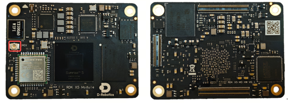
1.1.3 RDK X5 Module
The RDK X5 Module, equipped with the Sunrise 5 intelligent computing chip, provides up to 10 Tops of computing power. It is an all-round development kit for intelligent computing and robotics applications. It features rich interfaces and is extremely easy to use. It supports a variety of complex models and the latest algorithms, including Transformer, RWKV, Occupancy, and Stereo Perception, accelerating the rapid implementation of intelligent applications.
For example:
- Object detection algorithms such as FCOS, YOLO, FasterRCNN, Efficientdet, Mobilenet_ssd;
- Image classification models such as Mobilenet
- Semantic segmentation models such as Unet
- Application algorithm models such as human detection and tracking, gesture recognition, human hand key point detection, monocular elevation network, monocular 3D detection, speech processing, etc.
For more software algorithm applications, please refer to the official D-Robotics community documentation https://developer.d-robotics.cc/rdk_doc/RDK
The following are the main specifications:
| Specifications | |
|---|---|
| CPU | 8x A55@1.5GHz |
| RAM | 8GB LPDDR4 |
| BPU | 10 TOPS |
| GPU | 32Gflops |
| Storage | 32GB eMMC |
| Multimedia | H.265/H.264 |
| Power | 5V/5A |
| System | Ubuntu 22.04 |
Core
The RDK X5 Module carrier board provides a set of 300-pin board-to-board connectors for core module installation. During installation, ensure proper orientation and positioning to avoid damage to the core module and carrier board connectors.
The module installation method is as follows:
- Compare the core module pins to confirm the correct installation direction.
- Place the core module directly on top of the carrier board and ensure that the four positioning holes around it are aligned.
- Press down from the center of the core module until the module clicks into place.
Power
To facilitate SSH debugging when 5V/5A power adapter or a computer USB port is required to power the carrier board.
If you need to connect other external devices such as a mouse, keyboard, monitor, camera, radar, or other sensors, you need to use the AI PWR's XT30 port to power the device through the matching USP10 power module.
After connecting the power adapter to the development board, the green 5V indicator PWR indicator lights up, indicating that the development board is powered normally, and the green ACT indicator flashes, indicating that the system is running normally.
Wired network
The development board provides a Gigabit Ethernet port that supports 1000BASE-T and 100BASE-T standards. By default, it uses static IP address 192.168.127.10. To confirm the IP address of the development board, log in to the device through the serial port and use ifconfig the command to view eth0 the network port configuration.
HDMI display
The development
USB
The development board implements multi-channel USB interface expansion through hardware circuits to meet the user's needs for accessing multiple USB devices. The interface description is as follows:
| Interface Type | Interface Name | Number of interfaces | Interface Description |
|---|---|---|---|
| USB 2.0 Type C | AI USB 2.0 | 1st Road | USB Device mode, used to connect to the host to implement ADB, Fastboot, system burning and other functions |
| USB 3.0 Type C | AI USB 3.0 | 1st Road | USB Host mode, used to connect USB 3.0 peripherals |
Connect USB
The AI development /media/sda1.
Connecting to the USB serial port adapter
The AI development /dev/ttyUSB* ( /dev/ttyACM* asterisks represent numbers starting at 0). For more information on using the serial port, refer to the Using the Serial Port section.
USB
The AI development /dev/video0.
CSI Camera
The core board provides two CSI interfaces, CAMERA1 and CAMERA2, which can connect two cameras and support binocular cameras. Currently, the module is compatible with a variety of camera modules. The module models and specifications are as follows:
| Serial number | Sensor | Resolution | FOV | I2C device address |
|---|---|---|---|---|
| 1 | IMX219 | 800W | ||
| 2 | OV5647 | 500W | ||
| 3 | IMX477 | 1230W |
After the installation is complete, users can use the i2cdetect command to confirm whether the module's I2C address can be detected normally.
Query the I2C device address of the Camera Sensor on the CAMERA1 interface:
echo 353 > /sys/class/gpio/exportecho out > /sys/class/gpio/gpio353/directionecho 0 > /sys/class/gpio/gpio353/valuesleep 0.1echo 1 > /sys/class/gpio/gpio353/valuei2cdetect -y -r 6
Query the I2C device address of the Camera Sensor on the CAMERA2 interface:
echo 351 > /sys/class/gpio/exportecho out > /sys/class/gpio/gpio351/directionecho 0 > /sys/class/gpio/gpio351/valuesleep 0.1echo 1 > /sys/class/gpio/gpio351/valuei2cdetect -y -r 4
When the I2C device address of the Camera Sensor is successfully detected, you can see the following printout (taking the detection of IMX219 on CAMERA2 as an example, you can find that address 10 is printed out):
root@ubuntu:~# i2cdetect -y -r 4
    0  1  2  3  4  5  6  7  8  9  a  b  c  d  e  f
00:                         -- -- -- -- -- -- -- --
10: 10 -- -- -- -- -- -- -- -- -- -- -- -- -- -- --
20: -- -- -- -- -- -- -- -- -- -- -- -- -- -- -- --
30: -- -- -- -- -- -- -- -- -- -- -- -- -- -- -- --
40: -- -- -- -- -- -- -- -- -- -- -- -- -- -- -- --
50: -- -- -- -- -- -- -- -- -- -- -- -- -- -- -- --
60: -- -- -- -- -- -- -- -- -- -- -- -- -- -- -- --
70: -- -- -- -- -- -- -- --
Wi-Fi antenna
The development board's wireless network supports both onboard and external antenna configurations. The onboard antenna is generally sufficient for wireless communication. When the development board is mounted in a metal enclosure, you'll need to connect an external antenna to the core board to enhance signal strength.
CANFD
RDK X5 Module provides a CANFD interface, which can be used for CAN and CAN FD communication. For more information, please refer to the CAN Usage section.